Before you start
This is the first chapter of the kit "Game & Watch from transistors". We'll go from a single glowing digit to a real electronic HH:MM watch — with a blinking colon and time setting. Everything is built by hand, from logic gates, in a browser simulator, on a segment LCD — like Nintendo's handheld games and 1980s CASIO watches.
The watch is not the goal but a warm-up. It trains everything the game will need later: a digit decoder, memory, counters, carry, count enable, a button-press detector, and working with real time.
What we build in the end
This is where the kit leads — the game "Star Harvest" (a working title) with a watch in the corner, like a real Game & Watch. Try it right here:
An astronaut on a space station catches crystals rolling out of four pipes. Each button puts him at its pipe at once: Q / A — the left pipes (top / bottom), P / L — the right ones, Space or START — a new game. Miss a crystal — a miss; three misses — game over. The more points, the faster the crystals roll, and while a comet is in the porthole every crystal is worth two. The clock in the left corner is this chapter's machine.
Here the game runs as a program — it is a model that repeats the future circuit tick by tick. In the kit the same machine is built from gates: the screen, the watch, the score counters, the shift registers of the pipes, a random generator, buzzers — about 8–9 thousand transistors in all. Chapter 1 is its first half: the watch.
What you need to know beforehand: nothing beyond school arithmetic. Binary numbers, logic gates and memory are explained along the way.
How to read it: the lessons go strictly in order, each continuing the previous one. Every lesson has an explanation, the derivation of the formulas and build tables: they place the circuit on the canvas one element at a time. At the end of each lesson there is a check and a text to paste with Cmd+I if you want to build the lesson in one move.
The simulator in five minutes
The first light
Open cs.khanin.info — that's our simulator. Five minutes of hands-on before you read on:
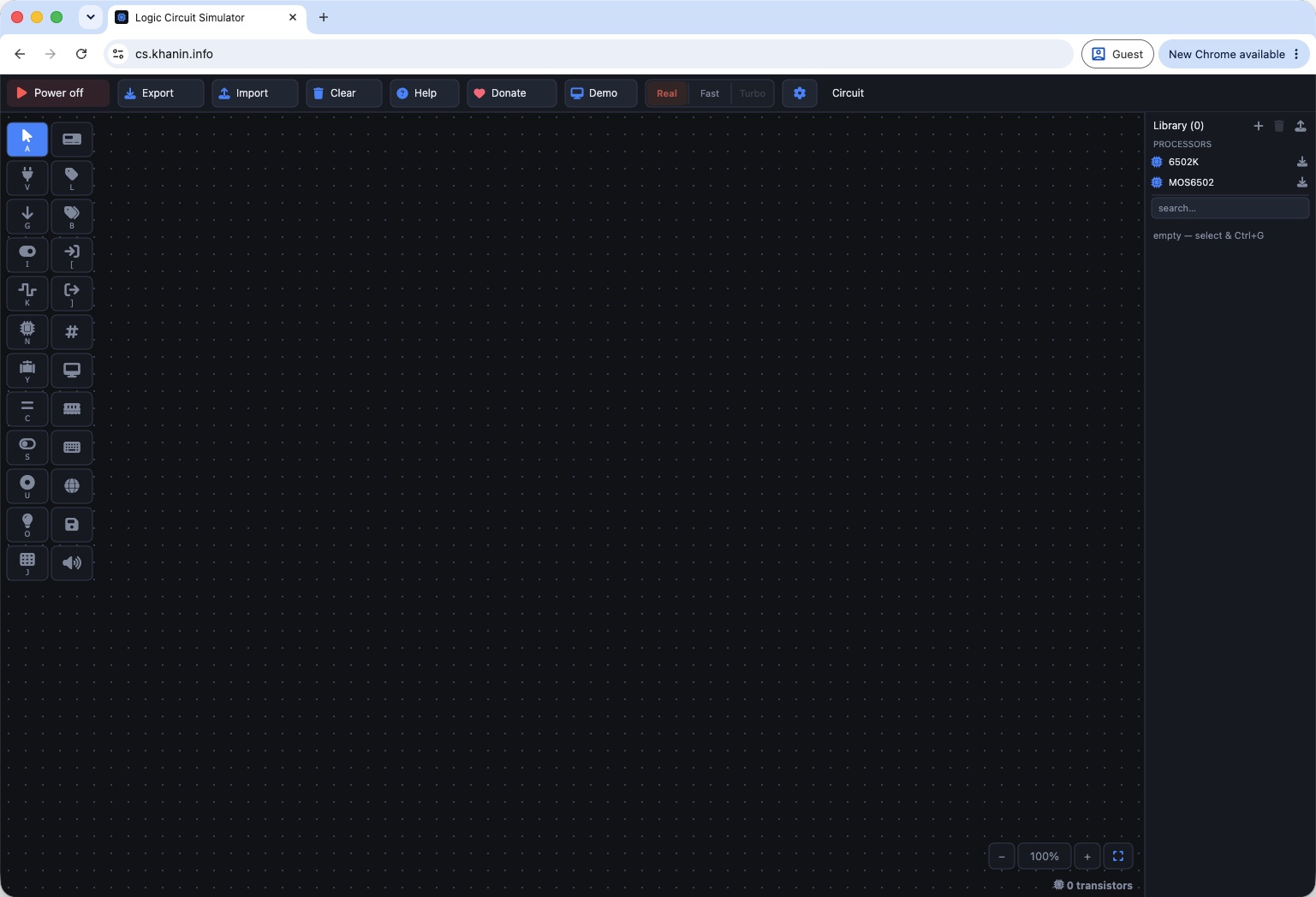
- 1 Power: turns the circuit on and off
- 2 Export / Import: save the project to a file and open it
- 3 engine: Real — every transistor, Fast — faster; Turbo is for processors, not needed in this kit
- 4 parts palette; the letter under a button is its key (V, G, I, K, N, O, L…)
- 5 canvas — parts go here
- 6 library: your chips appear here (Ctrl+G); the 6502 processors are for other kits
- A source of one. Press
Vand click the canvas — aVCCappears, a source of 1 ("the plus of a battery"). - A transistor. Press
Nand click next to it. A transistor has three pins: the gate on the left, top and bottom. The letter on the body isN; if it saysP, click the body. - A lamp and a switch.
O— lamp,I— switch. - Wires. Drag with the mouse from pin to pin:
VCC→ transistor top, bottom → lamp, switch → gate. - Turn the power on — the Power button, first on the left of the top bar — and click the switch. Switch 1 — the lamp is on, 0 — off. A transistor is a switch controlled by a signal. Everything in this kit, up to the game, is built from such switches.
- Labels instead of wires. Delete the wire from the switch to the gate (click the wire and press
Delete). PressL, place a label and wire it to the switch pin; name itA(double-click a label to rename it). Wire a second labelAto the gate. It works just like the wire: labels with the same name are connected. Every build table in the kit relies on this. - Save: the Export button on the top bar.
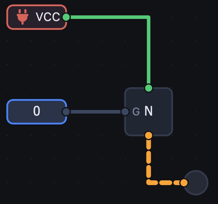
switch 0 — the lamp is off, its wire "floats" (amber dashes)
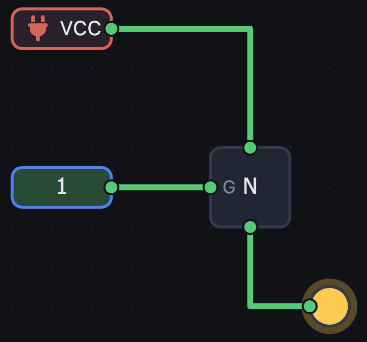
switch 1 — the transistor conducts, the path is green, the lamp is on
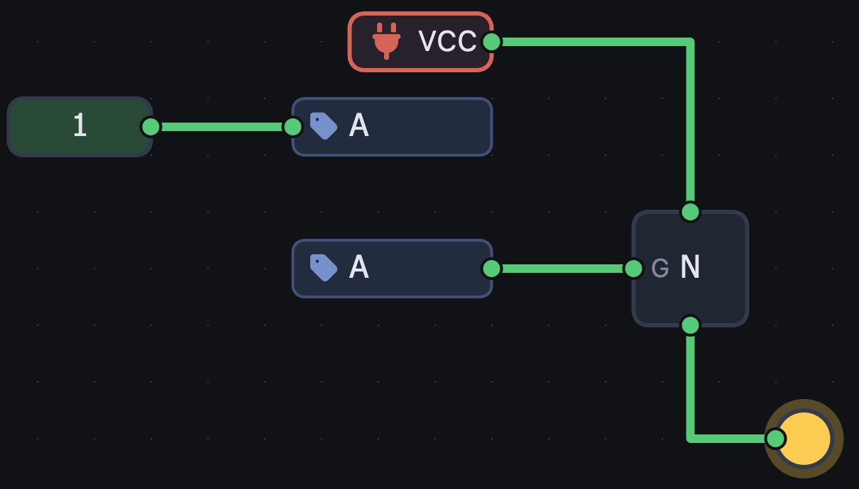
Did you notice that with the switch off the wire to the lamp turned into an amber dashed line? At that moment the lamp is connected to nothing — it "floats". Here it's harmless, but in big circuits it's not allowed. In lesson 0 we'll see how a pair of transistors, N and P, solves this.
Not lighting up? The power is off (button on the bar); the transistor's top and bottom are swapped; the body says P instead of N — click the body to change the type.
The main things about the simulator
Canvas and palette. On the left is the parts palette, on the right the chip library. It starts empty: everything you build and fold into a chip appears there; you will build the basic gates NOT, NAND, NOR, AND, OR, XOR from transistors in lesson 0. Click the canvas to place a part. Useful keys: I — switch (Input), K — generator (Clock), L — label, [ / ] — chip input / output port, U — button, V / G — power / ground.
Labels instead of wires. A label is a signal's name. All labels with the same name are connected, even with no wire between them. That's why the build tables say not "a wire from here to there" but "put label X on this pin". You can draw wires too: drag from pin to pin.
How to read a build table. One row — one part. On the left, what goes into its inputs; on the right, which label its output gets:
| Element | Inputs | Output |
|---|---|---|
| AND | D0, D1 | D0D1 |
means: place an AND gate, labels D0 and D1 on its two inputs, label D0D1 on its output. For chips with named pins we write NAME=label: CNT10E with CLK=CLK, RST=tRST — label CLK on pin CLK, label tRST on pin RST.
Chips. A finished piece of circuit is folded into a chip: place ports ([ input, ] output), name them, select everything and press Ctrl+G. The chip appears in the library and can be placed any number of times. Double-click a chip to look inside; the Edit button changes it (all its copies change at once).
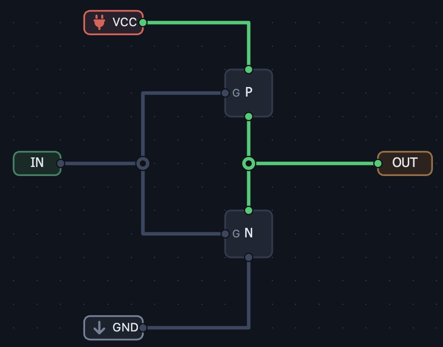
inside the NOT chip (double-click the chip): ports, the P and N transistors, VCC, GND
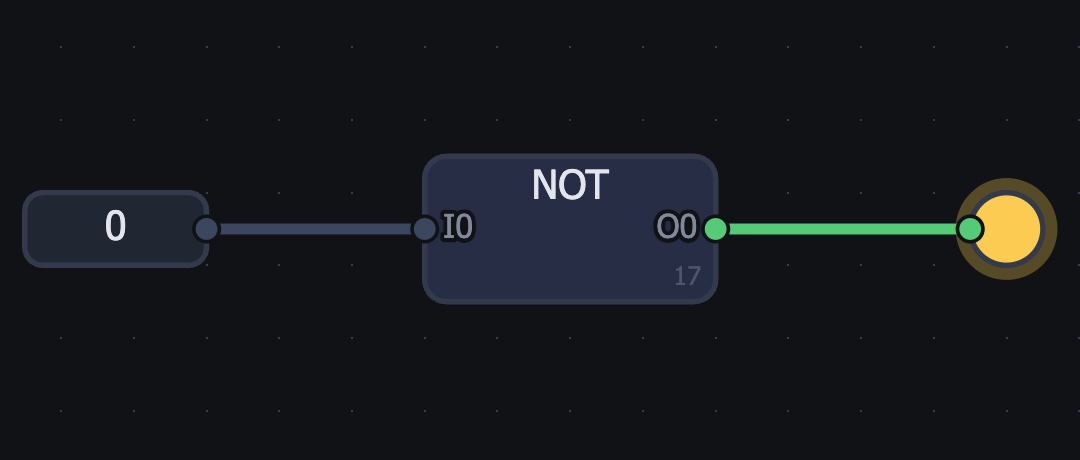
the NOT chip on the canvas: 0 in — the lamp on the output is on
Power and engines. The power button is on the left of the top bar. The engine (also on the bar): Real computes every transistor — exact but slow; Fast works by gates — much quicker. Both are fine for checking a circuit.
The generator (Clock). Clicking its body changes the frequency: 1Hz, 2Hz, 10Hz, 60Hz — real time (exactly that many ticks per second, for watches and games) and 4kHz … 64kHz, MAX — fast ones, for processors.
The segment LCD. A screen of drawn segments; every segment is its own pin (1 — visible). The gear ⚙ on the body opens the editor: ready-made digit stamps, magic-wand selection, turning a segment into a pin (Enter — New pin).
Checking. The T key — the truth table of the selected chip (for circuits without memory). The W key — the oscilloscope: it shows how signals change over time and helps find where a mistake is.
Paste as text (Cmd+I, on Windows Ctrl+I). Instead of building by hand you can paste a ready text — it's at the end of every lesson. But the point of the kit is to build it yourself: the paste is there to check your work or to catch up on a missed lesson. (Likewise, on a Mac Ctrl+G also works as Cmd+G.)
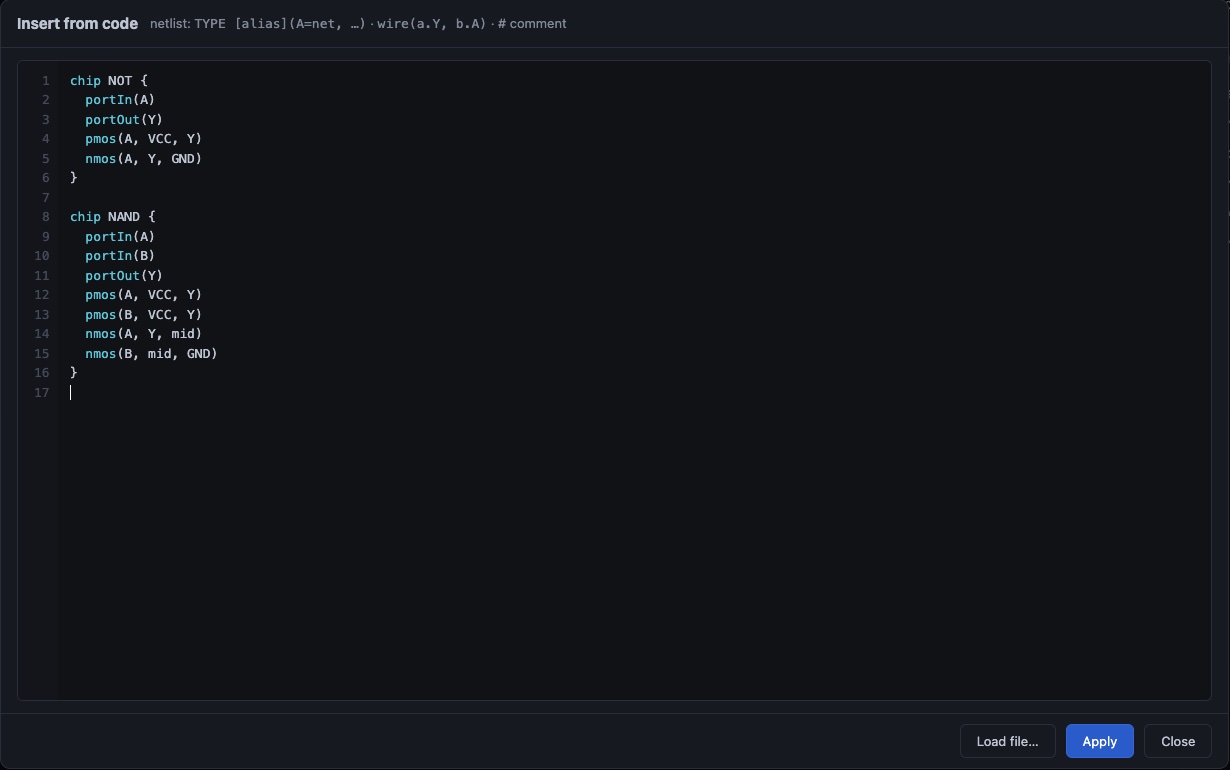
- 1 paste the text from the end of the lesson here (the "copy" button above it)
- 2 Apply — the circuit appears on the canvas, the chips in the library
- 3 Load file — the same from a file
Export. The Export button on the top bar saves the project to a file — do it after every lesson.