Something doesn't work
Common problems and what to do about them. Look for what you see on the screen.
Nothing changes, the switches do nothing
The power is off — the Power button, first on the left of the top bar. While it's off, the circuit isn't computed.
What the wire colours mean
The wire is an amber dashed line
That's Z: the pin is connected to nothing, the signal "floats". Usually:
- a wire or a label is missing;
- a typo in a label name. Case matters:
Aandaare different labels, so areCLKandClk. This is the most common mistake; - a chip input isn't driven — check every pin against the build table.
The wire is red
That's X: two outputs are connected and fight — one pulls to 1, the other to 0. Usually:
- the same label is on two outputs. Every signal must have exactly one source;
- two labels with different names got connected by accident — by a wire or by sitting on the same pin. Then it is one signal under two names: everything connected to both labels has merged. Look for a wire between labels or a pin that has two of them.
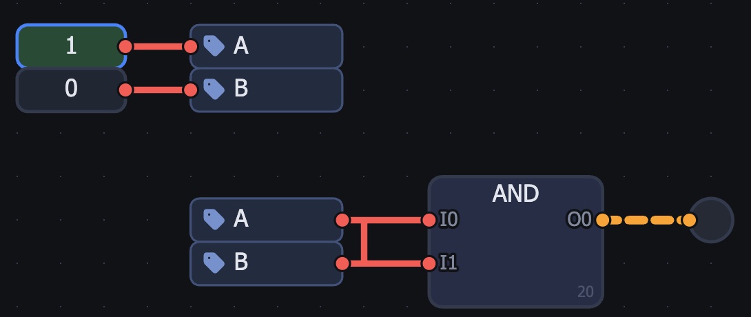
- 1 the stray wire: it joined labels A and B — now it is one signal, and the switches pull it to 1 and to 0
The lamp or the screen doesn't react
- the transistor's top and bottom are swapped;
- the body says
Pinstead ofN(or the other way round) — click the body to change the type; - a label is on the wrong pin — check the build table: the pin name on the left, the label on the right.
The chip is built but the pins are wrong or missing
A chip's pins are ports: [ — input, ] — output. Every port needs a name (double-click). No port — no pin; an input placed instead of an output — the pin is on the wrong side. To fix: double-click the chip → Edit.
A big circuit runs very slowly
Switch the engine on the top bar from Real to Fast. Real computes every transistor — exact but slow; Fast works with gates and is many times faster. Both are fine for checking a circuit.
My work is gone
The simulator saves your work by itself — in this browser. In another browser, a private window, on another computer or after clearing browser data it won't be there. So after every lesson — Export (a file on your disk); to bring the work back — Import.
I can't see where the mistake is
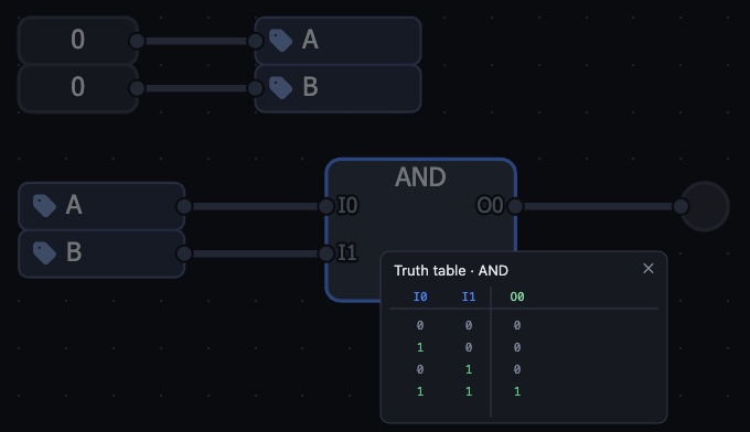
- select a chip and press
T— the truth table; compare it with the lesson; W— the oscilloscope: shows how signals change over time;- open a new empty project, paste the lesson's ready circuit (
Cmd+I, the text is at the end of the lesson) and compare it with yours: wherever they differ, that's the mistake.
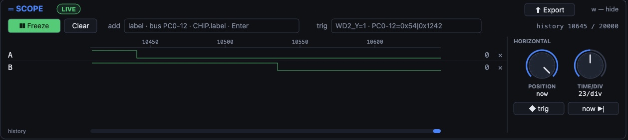
- 1 Freeze — stop recording to look closely
- 2 add — a label name and Enter: the signal gets its own row
- 3 signals over time: high is 1, low is 0; you can see who switched when
- 4 knobs — time position and scale
Completely stuck
Write to me on Telegram: @daniilkhanin — send the lesson number and what you see (a screenshot helps). English and Spanish are fine.